Mimic Diagrams
A mimic diagram is a graphical operator interface that represents a real-time schematic representation of a technological process or control object. It displays the current status of equipment, parameter values, and the relationships between system elements using symbols and animated elements.
In Rapid SCADA terms, a mimic diagram is a view. Mimic diagram elements are bound to channels and display the state of an automation object based on current data.
Plugin Settings
The operation of mimic diagrams is provided by several plugins of the Webstation application:
- Mimic Diagrams Plugin (PlgMimic) is responsible for mimic diagrams in runtime mode.
- Mimic Editor Plugin (PlgMimicEditor) allows users to create and modify mimic diagrams.
- Basic Mimic Components Plugin (PlgMimBasicComp) provides a minimum set of the necessary components.
- Extra Mimic Components Plugin (PlgMimExtraComp) extends the library with additional components.
The PlgMimic.xml configuration file contains settings used by the Mimic Diagrams and Mimic Editor plugins. This file is included in the project template, so when a new project is created, the configuration file is added with default settings. Mimic component plugins do not require configuration.
The following table describes the contents of the PlgMimic.xml file:
| XML element | Description |
|---|---|
| GeneralOptions | Section for the main parameters of mimics used in runtime and edit modes. |
| CustomCss | Path to the custom CSS file. |
| CustomJs | Path to the custom JavaScript file. |
| Fonts | Section for the fonts used by mimics. |
| Font | Element that defines a font. |
| name | Name of the font in the editor. |
| family | Font family designation in the HTML document. |
| url | Path to the font CSS file. |
| RuntimeOptions | Section for runtime parameters. |
| ScaleType | Default scaling type. |
| ScaleValue | Default scale value. |
| RememberScale | Saves the scale. |
| ShowToolbar | Displays the mimic toolbar. |
| BlinkingRate | Blinking rate of components in milliseconds, if the corresponding property is set. |
| EditorOptions | Section for editor parameters. |
| UseGrid | Uses a grid for component layout. |
| ShowGrid | Displays the grid. |
| GridStep | Grid step in pixels. |
Paths to custom CSS and JavaScript files, specified by the CustomCss and CustomJs options, begin with a tilde, which denotes the root of the web application. These paths may be empty. The custom files themselves must be located within the ScadaWeb\wwwroot\ directory. To add multiple style and script files, merge them into a single file using third-party tools.
Creating Mimic Diagram
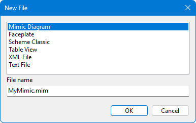
To create a new mimic diagram, go to the Views section of the project in the Administrator application, right-click the desired folder, and select New File from the context menu. In the window that opens (see Figure 1), select the Mimic Diagram view type, specify a file name, and click OK. The created file will appear in the project explorer.
Once the view file is created, double-click the file to open it in a web browser in Mimic Editor. The Webstation application must be installed and running on the same computer where the Administrator application is running.
Components
A component is an interactive graphic object within a mimic diagram that dynamically displays the state of a specific device or parameter in real time and allows for its manipulation. It is the building block of a mimic diagram.
Components in Mimic Editor are divided into groups depending on the plugin they are implemented in. Components in the Standard group are implemented in Mimic Diagrams Plugin. Components in the Basic and Extra groups are implemented in plugins with corresponding names.
The table below contains a brief description of the components.
| Component | Description |
|---|---|
| Standard components | |
| Panel | Designed to host child components for grouping purposes. Can be nested within one another. |
| Picture | Displays a graphic. The picture can be static or dynamic based on specified conditions. The recommended format is SVG. PNG and GIF formats are also supported, including animated graphics. |
| Text | Displays a text string. The text can be static, display a bound channel value, or switch dynamically based on conditions. |
| Basic components | |
| Button | Represents a control button used to issue telecontrol commands, trigger pop-up windows, or execute other actions. |
| Led | A circular or rectangular status indicator that changes its color according to the value of a bound channel based on predefined conditions. |
| Toggle | A two-position switch that transmits telecontrol commands when toggled. |
| Extra components | |
| Frame | Designed to embed external web pages into a mimic diagram, including charts or other views. |
| Gauge | An analog dial instrument. The background graphic, scale, and pointer needle are fully customizable. |
| Level | Displays the current value of a bound channel as a vertical or horizontal fill level. |
| Markup | Designed for embedding custom HTML code snippet blocks. Highly useful for building custom faceplates. |
| Trend | Plots a real-time historical trend chart of a given parameter. |
Faceplates
A faceplate is a user-created component based on other components for reuse in various mimic diagrams. Changes made to the faceplate are reflected in the mimic in which it is used.
Faceplates are created from the Administrator application and edited in Mimic Editor, similar to mimics diagrams. To create a faceplate, open the file creation dialog described above (Figure 1), select the Faceplate type, specify a file name, and click OK. Then, double-click the created file to open it in the editor.
Faceplates can export user-defined properties. The corresponding faceplate property in the editor is called Exported properties. When a faceplate is added to a mimic diagram, custom properties for the faceplate instance are created based on the exported properties and displayed in the properties table in the Misc category.
Each exported property is a structure whose fields are described in the following table:
| Field | Description |
|---|---|
| Property name | Required field. Can contain Latin characters and numbers, must start with a letter, periods are not allowed. |
| Path | Links the exported faceplate property and the target property of the child component. Contains the name of the child component and its property name, separated by periods. When the value of the exported property changes, the target property changes. The value of the target property is used as the default value for the exported property. |
| Default value | Used if the path is empty and the exported property is handled by a script. |
| Default binding | Helps to preconfigure the data binding that is created in the faceplate instance when it is added to the mimic diagram. |
Data Binding
To dynamically display a parameter value in real time, component properties must be bound to data. Each component has a corresponding list property called Property bindings.
Structure of a single property binding:
| Field | Description |
|---|---|
| Property name | Required field. For properties with a complex structure, the full name is separated by periods. |
| Data source | This is the channel number, part of the channel code, or the tag code. |
| Data member | Determines which part of the channel data is used to build the property value. |
| Expression | Transforms the value using JavaScript. |
| Format | Transforms the string according to a format, for example, Hello {0} world. Works only for string properties. |
The argument passed to the expression depends on the data member selected. After the expression is evaluated, the format, if specified, is applied to the result.
| Data member | Expression argument | Expression example |
|---|---|---|
| Value | Numeric channel value or Number.NaN if the channel status is 0 |
isNaN(x) ? "None" : x * 2 |
| Status | Channel status, a number | |
| Data | Channel value and status, an object { val, stat } |
x.stat > 0 ? x.val * 2 : "None" |
| Display value | String | "Value: " + x |
| Value with unit | String | "Value and unit: " + x |
| Main color | String | |
| Second color | String | |
| Back color | String |
Binding component properties works differently depending on which property from the Data category is set:
- The Object number is specified. The Data source field in the binding contains a portion of the channel code. The application determines the channel number as follows: a string from the data source is appended to the object code, and the channel is searched for by the code among the channels of the specified object.
- The Device number is specified. The Data source field in the binding contains the tag code. The channel number is determined by the device number and tag code.
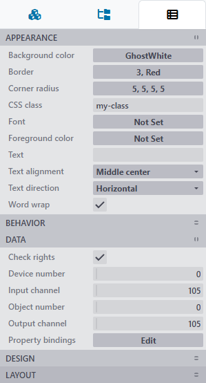
- The Input channel is specified. If the object or device number is not specified, the data source in the binding must contain a specific channel number.
For some properties, data binding is not available. These are properties from the Data and Design categories, scripts. Such properties are marked in gray in the property selection dialog.
Default Property Binding
Many components support simplified default property binding. If the Input channel property is specified, the component can implicitly bind its properties to the data in that channel. If binding for a component property is explicitly specified, no default binding is created for that property.
For example, if an input channel is specified for a Text component, its text and color will be displayed according to the channel value and status. The value is displayed with the unit. Therefore, for a text component, default bindings are created for the Text and Main color properties.
Scripts
Mimic Diagram and Component Scripts
The Script property is available for a mimic diagram, faceplates, and all components. Scripts are designed to implement custom functionality. If a custom script contains an error, the mimic diagram remains operational.
All custom scripts must inherit from the ComponentScript base class, which provides the following methods:
| Method | Arguments | Description |
|---|---|---|
domCreated(args) |
{
  mimic,
  component,
  renderContext
} |
Called once immediately after the mimic or component DOM is created. For a faceplate, this method is called after similar methods of its components have been called. |
domUpdated(args) |
{
  mimic,
  component,
  renderContext
} |
Called immediately after the component DOM is updated. For a mimic diagram, this method is not actually called. For a faceplate, it is called after similar methods of its components have been called. |
dataUpdated(args) |
{
  mimic,
  component,
  dataProvider,
  propertyChanged,
  handled
} |
Called for a component after its data is updated. For a mimic diagram, this method is called after all component data is updated. If a component property has changed, set args.propertyChanged = true to visually update the component. Setting args.handled = true prevents the component's own script from being called. |
getCommandValue(args) |
{ component } |
Returns the command value to be sent. This method is called when sending a command without displaying a dialog box. |
The domCreated and domUpdated methods are called for the mimic, components, and child components of faceplates in both runtime and edit mode. However, if the faceplate itself is open for editing, these methods are not called to avoid argument ambiguity: args.component is available in runtime, while args.mimic is available when editing.
Example of a custom script for a Text component:
class extends ComponentScript {
  domCreated(args) {
    console.log("DOM created for component " + args.component.id);
  }

  domUpdated(args) {
    console.log("DOM updated for component " + args.component.id);
  }

  dataUpdated(args) {
    const props = args.component.properties;
    const cnlData = args.dataProvider.getCurData(props.inCnlNum);
    const blinking = cnlData.d.stat > 0 && cnlData.d.val >= 10;

    if (props.blinking !== blinking) {
      props.blinking = blinking;
      args.propertyChanged = true;
    }
  }
}
Action Script
An action script is a script that executes when a component is clicked. The script is compiled Just-in-Time when the action is called. The script code must contain a function, for example:
function (args) {
  args.renderContext.viewHub.features.chart.show(args.component.properties.inCnlNum);
}
The function argument is an object { component, renderContext }
Mimic Editor
Mimic Editor is a plugin running under the Webstation application. The editor opens mimic and faceplate files located locally on the same computer where the Administrator and Webstation applications are installed. The Administrator role is required for a web application user to edit mimics.
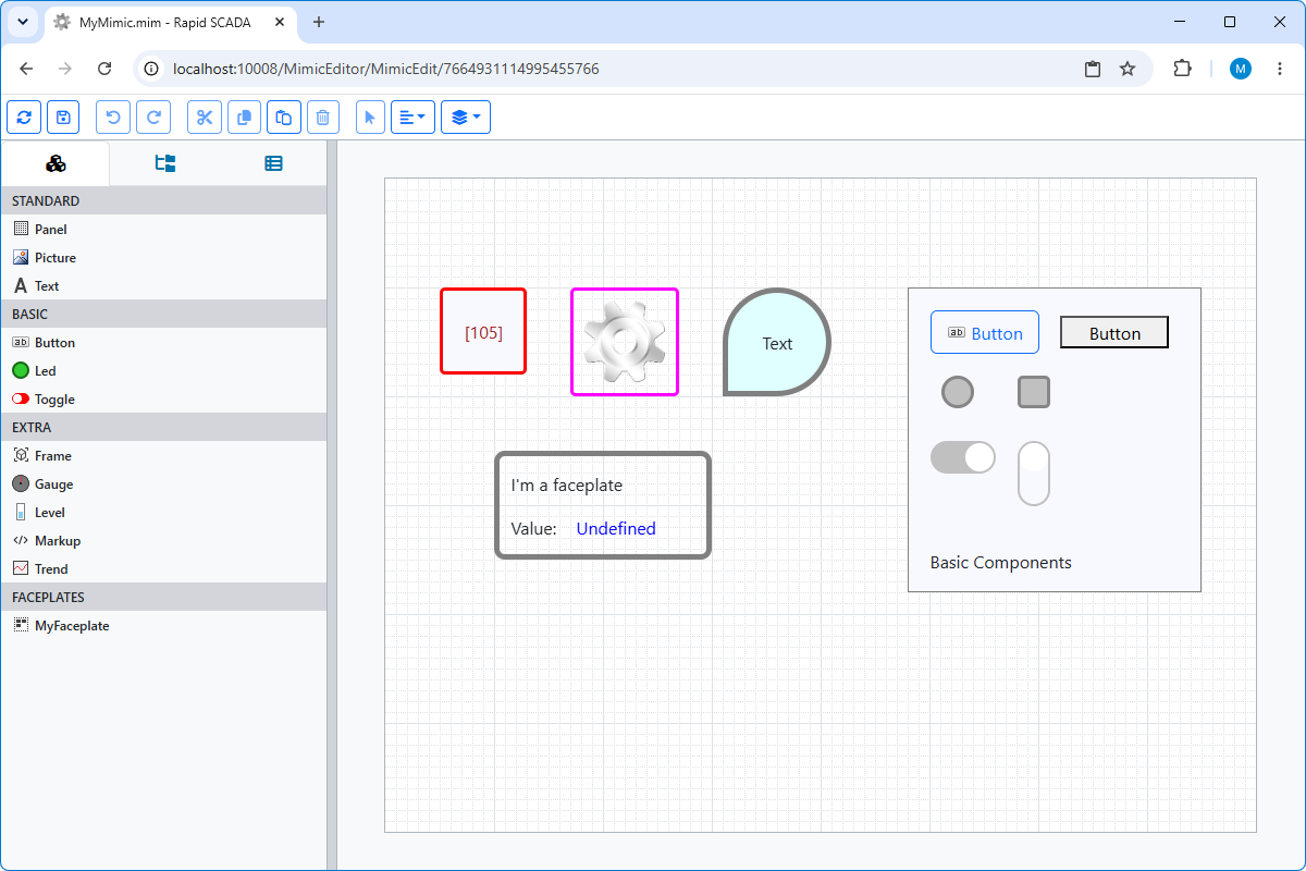
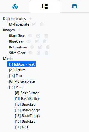
At the top of the web page is a toolbar with buttons for performing basic actions. On the left are tool windows: Components, Structure (Figure 3), and Properties (Figure 4). In the central part of the web page is an editable mimic diagram.
The most convenient way to open a mimic diagram in the editor is to double-click the file being edited in the Administrator application. Alternatively, open the mimic through the web application by selecting Main Menu > Mimic Editor > Active Mimics and specifying the path to the file on disk.
Important
When a project is uploaded for execution, the web application restarts, and open mimic diagrams are closed without saving changes. This feature must be taken into account.
Changing Location and Size of Components
Components are selected by clicking on a component in the mimic or structure window. To select multiple components, hold down the Ctrl key and left-click.
Selected components can be moved by dragging with the mouse or using hotkeys:
- The arrow keys move the selected components by the grid size.
- While holding down Ctrl, the arrow keys move components by 1 pixel.
- While holding down Shift, use the arrow keys to resize components.
Mimic Templates
The same mimic diagram file *.mim can be used to create multiple mimic views whose channels and title differ from the original. Such a file is called a mimic template.
To use a mimic diagram as a template, set the Arguments field in the Views table. Example of view arguments: cnlOffset=100&titleCompID=1, where
cnlOffset is the channel number offset,
titleCompID is the identifier of the text component for displaying the title.
Arguments are applied on the server side when the view is loaded. Channel number offset is performed if the channels for a component are specified explicitly, and the object and device numbers in the component properties are equal to 0. The title text for a mimic diagram operating on a template basis is taken from the Title field of the Views table.