Device Polling
Interaction with devices is performed by the Communicator application, which requests data and sends commands to devices, acting as a master or slave. The polled devices are controllers, input/output modules, metering devices, as well as external data sources, which are also conventionally called devices. All devices belong to communication lines that are independent and operate in parallel.
Devices are polled using various communication protocols, such as Modbus, OPC or MQTT. Each protocol is implemented by a corresponding driver. Some drivers are installed by default during the Rapid SCADA installation process. Other drivers can be installed additionally.
Communication Line Options
Figure 1 shows an example of setting up the main options of a communication line. Pay attention to the communication channel settings. A communication channel defines a physical interface or network protocol used to poll devices. The following communication channels are supported: Serial port, TCP client, TCP server, UDP and MQTT client. In some cases, if device connection is implemented directly by a driver (for example, OPC), the communication channel should be left unspecified.
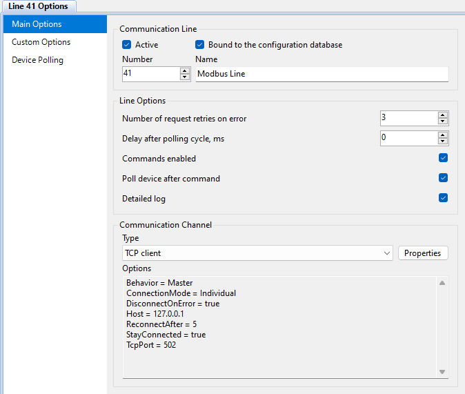
Custom line options are specific to the driver being used. They are configured using a user interface implemented by the driver, or can be set according to instructions for a certain device type.
Device Options
In the Device Polling section, individual polling options are configured for each device related to the communication line.
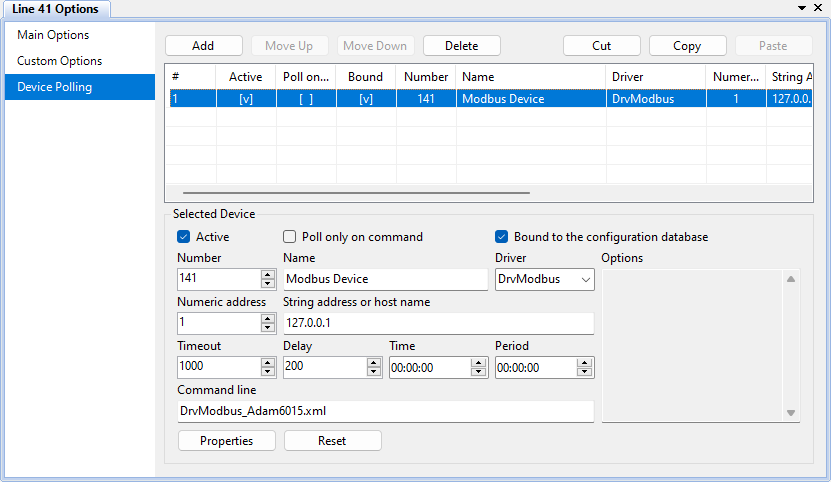
The table below clarifies the device polling options.
| Option | Description |
|---|---|
| Active | Indicates that the device is being polled |
| Poll only on command | To poll the device, send a command |
| Bound to the configuration database | If the option is set, the device tags are bound to the channels of the configuration database, and the received data is sent to the Server application |
| Number | Device number. It must match the device number in the configuration database |
| Name | Device name |
| Driver | A driver that implements the communication protocol supported by the device |
| Numeric address | Device address as a number |
| String address or host name | Device address as a string. This is usually an IP address |
| Timeout | Duration of waiting for a response from the device in milliseconds |
| Delay | Delay after receiving data in milliseconds |
| Time and Period | If both options are zero, the device is polled continuously and cyclically. If the time is specified and the period is zero, the device is polled once a day at the specified time. If the period is greater than zero, the device is polled periodically, starting at the specified time |
| Command line | Additional options determined by the driver and described in its instructions |
| Options | Similar to command line, but more structured |
If the device requires device type-specific options, click the Properties button to then to configure them in a dialog window provided by the driver. The Reset button restores the device polling options to the default values determined by the selected driver.
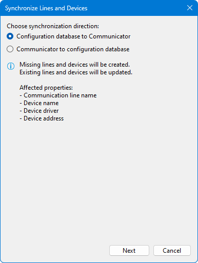
Synchronizing Settings
The synchronization feature helps create communication lines and devices in the Communicator settings based on data from the Communication lines and Devices tables of the configuration database. And vice versa, fill the configuration database tables based on the Communicator settings. To open the synchronization dialog, in the project explorer, right-click the Communication Lines node or the node of a specific line, then select Synchronize from the context menu.