Modbus Slave Driver
Overview
The driver implements the popular Modbus communication protocol and operates as a slave. Using the driver, Communicator waits for incoming requests and commands from a third-party device or application that acts as a master. Supported communication channels are serial port, TCP server and UDP. The driver can operate in either Modbus RTU or Modbus TCP mode. Download the driver using the link.
Modbus Slave Driver features:
- Receives data from a master device using write commands.
- Provides data to a master device in response to read commands.
- Works as a gateway, that is, the driver broadcasts channel values received from other devices.
Installation
Modbus Slave Driver is installed in accordance with the general sequence of installing drivers.
Configuring
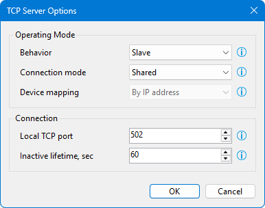
Create a new communication line using the wizard, which is called by the  button. Select the appropriate communication channel type and configure its properties. The following figure shows an example of the TCP server communication channel options.
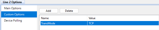
In the custom communication line options section, add the TransMode parameter, which is responsible for the data transfer mode. It can take RTU and TCP values.
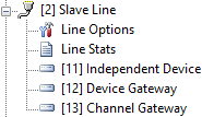
Using the wizard called by the  button, add one or more Modbus Slave type devices to the communication line. The numeric address of the device is important, it is the slave device ID according to the Modbus protocol specification. As an example, three devices operating in different modes were added, which are discussed below. The following figure shows a communication line node in the project explorer.
The Independent device mode is used if Communicator should receive data from a controller that is the master. To transmit information to Communicator, the controller writes data using Modbus functions 0x05 and 0x06. In addition, the controller can read previously written device tags from Communicator. Reading is performed using Modbus functions 0x01, 0x02, 0x03 and 0x04. A device tag can be written either by the master controller or by a control command sent by an operator.
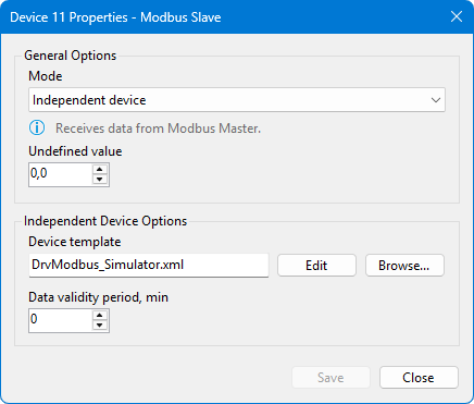
The Undefined value option specifies the value that is returned to the master if the requested register data is undefined. It applies to numeric registers and has no effect on flags. If a Data validity period is set, tag values will be reset to undefined if no new data is received from the controller for the specified period of time.
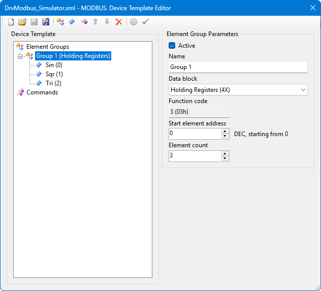
The Device template defines the structure and addresses of the Modbus registers. The template format used by Modbus Slave Driver (DrvModbusSlave) is identical to the device template format used by Modbus Master Driver (DrvModbus).
If the independent device mode is selected, after completing the device properties setup, create channels in the configuration database using the wizard called up by the  button. If another device mode is selected, creating channels is not required.
The Device gateway mode is used to provide the current channel data of the selected device to a third-party system.
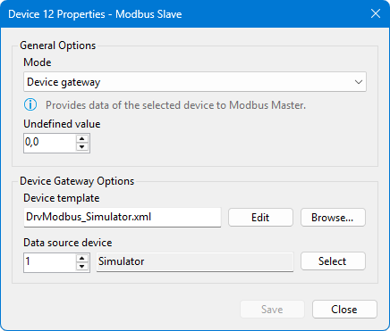
The channels of the data source device and tags of the gateway device are linked based on a comparison of the channel tag codes and the tag codes specified in the gateway template. If the data source device is polled via the Modbus protocol, the same device template can be used to operate the gateway.
If the master executes a write command to the gateway device tag, Communicator sends the corresponding command to Server on the channel associated with the tag. That command can then be passed to a physical device, whose data is transmitted by the gateway.
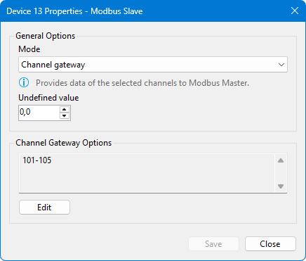
The driver operation in the Channel gateway mode is similar to the operation in the device gateway mode. The difference is that the channel gateway options explicitly specify the channel numbers whose data is being broadcast. The channel gateway options are shown in the following figure.
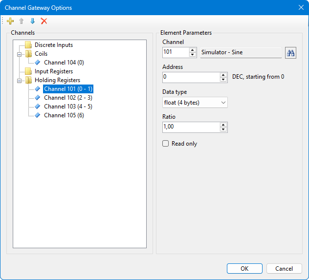
For each selected channel, specify the starting Modbus register Address and choose the Data type. The Ratio is used to transmit a real value of the channel as an integer with a certain number of decimal digits. The Read only parameter determines whether the gateway responds to an element write command received from the master.