Connecting Devices Using OPC Standard
This article describes how to configure communication with devices using OPC standard. OPC is designed to provide a common bridge for the software and process control devices from different manufacturers (see Wikipedia). Rapid SCADA supports the following OPC specifications:
- OPC DA (Data Access) to read and write current device data.
- OPC AE (Alarms & Events) to receive event notifications.
Rapid SCADA implementation of OPC client is provided by the Communicator application, to be exact, by KpOpc.dll driver. The goal of this article is learning about the details of Communicator configuring for using OPC.
The general configuration sequence:
- Download and install OPC Core Components. These components can be found at opcfoundation.org and rapidscada.org.
- Create an object, a communication line and devices in the configuration database.
- Configure communication between Communicator and OPC servers as described in this article.
- Create input channels in the configuration database according to the tags of the devices. Create output channels according to the commands.
- Create views (tables or schemes) to display data in the Webstation application. Define the views in the configuration database.
The details of the above steps, excluding the step #4, are described in the Software Configuration section. It is recommended to see the project DemoProject.en-GB, which is installed together with Rapid SCADA. Device 21 "OPC Demo" is an example of using OPC. The device tags are displayed by the table view OpcDemo.tbl. This example requires MatrikonOPC Simulation Server, which provides data.
Create a separate communication line for each OPC server that is used. This is the most efficient approach because it allows communicating with the OPC servers in parallel. Set Undefined communication channel type for the created communication lines in Communicator. Then add devices to the communication lines.
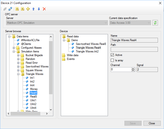
Go to the Communicator settings and open the device properties. The configuration form, shown in Figure 1, allows to select which OPC tags are received from OPC server.
OPC servers installed on the local computer are available to Communicator. If data from an OPC server, installed on another computer within a network, are required, deploy an extra instance of Communicator on that computer and properly configure it to connect to the Server application.
There are two ways how to bind OPC tags to input channels of the configuration database:
- Using the Signal field of device tags and input channels to identify tags.
- Setting input channel numbers directly in the configuration form shown in Figure 1.
Select the way that is more suitable in a particular configuration of an automated system.
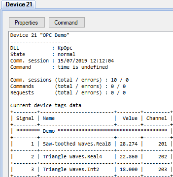
When the configuration is completed, upload the project to the server by the  button. Check OPC communication state and received data using Communicator logs (see Figure 2). If the data in Communicator seem to be true, open a browser and look for the same data in the Webstation application.
Known issue of using OPC: unable to receive data from OPC server while OPC tag properties are available in the device configuration form, no error messages are raised.
Possible reason is that the Communicator service operates as system user but OPC server forbids interacting with system user.
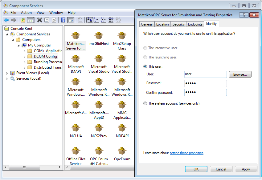
Solution 1. Specify a user account that is used to run OPC server. To open DCOM configuration (see Figure 3), follow the path Control Panel\System and Security\Administrative Tools\Component Services or just run comexp.msc
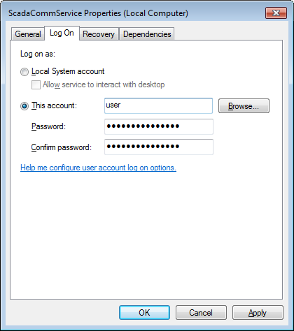
Solution 2. Specify a user account that is used to run the Communicator service. Go to Control Panel\System and Security\Administrative Tools\Services or run services.msc, find ScadaCommService and open the service properties. Then enter user account and password on the Log On page as shown in Figure 4. The specified user must be a computer administrator.